| |
|

|
|
|
|
|
|
|
|
|
|
|
|
|
|
|
|
|
|
|
|
|
|
|
|
|
| |
Wall
Thickness Calculation of Ellipsoidal Head Under Internal Pressure
|
| |
| |
ASME
Section VIII Div 1 - Appendix 1-4 - Formulas for the Design of Formed Heads
Under Internal Pressure (9)
|
| |
Appendix
1-4(c) Ellipsoidal Heads
|
|
|
| |
|
|
| |
|
(Enter values in yellow cells for calculations)
|
| |
DATA INPUT
|
| |
|
|
|
|
|
|
|
|
|
|
|
|
|
|
|
|
|
|
|
|
|
|
|
|
|
|
| |
|
Design Conditions
|
|
|
Material
|
|
|
|
| |
|
Design Pressure, Pd =
|
|
psig
|
Head
Material Specification (1 to 7)
|
|
|
|
| |
|
|
|
|
|
|
|
|
|
|
|
|
|
|
|
|
|
|
|
|
|
|
|
|
|
|
| |
|
Design Temperature, Td =
|
|
°F
|
Allowable
Stress Head, S =
|
|
psi
|
|
| |
|
|
|
|
|
|
|
|
|
|
|
|
|
|
|
|
|
|
|
|
|
|
|
|
|
|
| |
|
Welding Efficiency, E =
|
|
|
Dimensions
|
|
|
|
| |
|
See Table UW-12
|
|
|
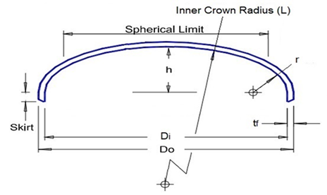
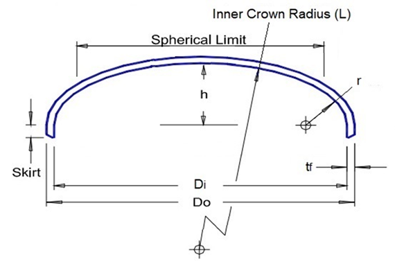
Inside
Diameter of the head skirt, Di =
|
|
in.
|
|
| |
|
Corrosion Allowance, CA =
|
|
in.
|
|
|
|
|
|
|
|
|
|
|
|
|
|
|
|
|
|
|
|
|
|
|
| |
|
|
|
|
Nominal wall
thickness before forming (8), tn =
|
|
in.
|
|
| |
|
|
|
|
|
|
|
|
|
|
|
|
|
|
|
|
|
|
|
|
|
|
|
|
|
| |
|
|
Minimum
specified thickness after forming (9), tf =
|
|
in.
|
|
| |
|
|
Minimum
required thickness after forming, tr =
|
|
in.
|
|
| |
|
|
|
|
|
|
|
|
|
|
|
|
|
|
|
|
|
|
|
|
|
|
|
|
| |
|
|
Inside depth of the ellipsoidal head with
corrosion removed, h (10) =
|
|
in.
|
|
| |
|
|
Head
Proportion = Di/2h (11) =
|
|
|
|
| |
|
|
Outside
Diameter of the head skirt, Do =
|
|
in.
|
|
| |
|
|
|
|
|
|
|
|
|
|
|
|
|
|
|
|
|
|
|
|
|
|
|
|
| |
|
|
Straight skirt length (12)(13), SK =
|
|
in.
|
|
| |
|
|
|
|
|
|
|
|
|
|
|
|
|
|
|
|
|
|
|
|
|
|
|
|
| |
|
|
Check If tr
≤ tn
|
|
|
|
| |
|
|
Check If tr
≤ tf
|
|
|
|
| |
|
|
|
|
|
|
|
|
|
|
|
|
|
|
|
|
|
|
|
|
|
|
|
|
|
|
| |
|
|
|
|
|
|
|
|
|
|
|
|
|
|
|
|
|
|
|
|
|
|
|
|
|
|
| |
|
|
|
|
|
|
|
|
|
|
|
|
|
|
|
|
|
|
|
|
|
|
|
|
|
|
| |
|
Notes:
|
|
|
|
|
|
|
|
|
|
|
|
|
|
|
|
|
|
|
|
|
|
|
|
|
| |
(1)
|
S ≤ 66.66% of σy
@ temp.
|
|
|
|
|
|
|
|
|
|
|
|
|
|
|
|
|
|
|
|
|
|
|
|
|
| |
(2)
|
S > 66.66% but < 90% of σy @ temp.
|
|
|
|
|
|
|
|
|
|
|
|
|
|
|
|
|
|
|
|
|
|
|
|
|
| |
(3)
|
(t ≤ 21/2)
|
|
|
|
|
|
|
|
|
|
|
|
|
|
|
|
|
|
|
|
|
|
|
|
|
| |
(4)
|
(21/2 < t ≤ 4)
|
|
|
|
|
|
|
|
|
|
|
|
|
|
|
|
|
|
|
|
|
|
|
|
|
| |
(5)
|
(4 < t ≤ 6)
|
|
|
|
|
|
|
|
|
|
|
|
|
|
|
|
|
|
|
|
|
|
|
|
|
| |
(6)
|
Tensile strength of
the Section IX reduced section tension test is not less than 100 ksi.
|
|
|
|
|
|
|
|
| |
(7)
|
Tensile strength of
the Section IX reduced tension test less than 100 ksi but not less than 95
ksi.
|
|
|
|
|
|
|
|
| |
(8)
|
It is recommended a nominal thickness before
forming 15% higher than the minimum specified thickness to ensure after
forming thickness is above it.
|
|
| |
(9)
|
As per UG-79 (d)(3)
The reduction in weld thickness after forming shall not exceed 1/32 in. (1
mm) or 10% of the nominal thickness of the adjoining surface, whichever is
less.
|
|
| |
(10)
|
For Ellipsoidal head 2:1 h = DI/4
|
|
| |
(11)
|
Head Proportion = Di/2h (Ratio between 3 and 1)
|
|
|
|
|
|
|
|
|
|
|
|
|
|
|
|
|
|
|
|
|
|
|
|
|
| |
(12)
|
As per UG-32(k) All
formed heads, thicker than the shell and concave to pressure, intended for
butt welded attachment, shall have a skirt length sufficient to meet the
requirements of Figure UW-13.1, when a tapered transition is required. All
formed heads concave to pressure and intended for butt welded attachment need
not have an integral skirt when the thickness of the head is equal to or less
than the thickness of the shell. When a skirt is provided, its thickness
shall be at least that required for a seamless shell of the same inside
diameter.
|
|
| |
(13)
|
As per UG-32(l)
Heads concave to pressure,intended for attachment by brazing, shall have a
skirt length sufficient to meet the requirements for circumferential joints
in Part UB.
|
|
| |
(14)
|
The formula for the
typical 2:1 elliptical head is listed in paragraph UG-32(c) of ASME Code
Section VIII, Division 1. The general formula for all elliptical heads within
the dimensional scope is addressed in Appendix 1-4. Factor K varies depending
on the shape of the ellipse.
|
|
| |
|
|
|
| |
|
|
|
|
|
|
|
|
|
|
|
|
|
|
|
|
|
|
|
|
|
|
|
|
|
| |
CALCULATIONS
|
| |
|
|
|
|
|
|
|
|
|
|
|
|
|
|
|
|
|
|
|
|
|
|
|
|
|
|
| |
|
Ellipsoidal Head
|
|
|
|
|
|
|
|
|
|
|
|
|
|
|
|
|
|
|
|
|
|
|
|
|
| |
|
with tf/L ≥ 0.002
|
|
|
|
|
|
|
|
|
|
|
|
|
|
|
|
|
|
|
|
|
|
|
|
|
| |
|
|
|
|
|
|
|
|
|
|
|
|
|
|
|
|
|
|
|
|
|
|
|
|
|
|
| |
|
Thickness after forming adjusted for corrosion, nt =
|
|
in.
|
|
nt = tf-CA
|
|
|
|
|
|
|
|
|
|
|
|
|
|
|
|
|
|
|
|
|
|
|
|
|
|
|
|
|
|
|
|
|
|
|
|
|
|
|
|
|
|
|
| |
|
Inner diameter with corrosion removed, D =
|
|
in.
|
|
D = Di + 2CA
|
|
|
|
|
|
|
|
|
|
|
|
|
|
|
|
| |
|
|
|
|
|
|
|
|
|
|
|
|
|
|
|
|
|
|
|
|
|
|
|
|
|
|
| |
|
Inside depth of the
ellipsoidal head with corrosion removed, h
|
|
in.
|
|
(For Ellipsoidal head 2:1 h = D/4)
|
|
|
|
|
|
|
|
|
| |
|
Head Proportion = D/2h
|
|
|
|
|
|
|
|
|
|
|
|
|
|
|
|
|
|
|
|
|
|
|
|
|
| |
|
Factor K (15)
|
|
|
|
(The value is obtained from Table 1-4.1)
|
|
|
|
|
|
|
|
|
| |
|
Factor K1
|
|
|
|
(The value is obtained from Table UG-37)
|
|
|
|
|
|
|
|
|
| |
|
Inside spherical or crown radius, L = k1D
|
|
in.
|
|
|
|
|
|
|
|
|
|
|
|
|
|
|
|
|
|
|
|
|
|
|
| |
|
Inside knuckle radius (16), r =
|
|
in.
|
|
|
|
|
|
|
|
|
|
|
|
|
|
|
|
|
|
|
|
|
|
|
| |
|
|
|
|
|
|
|
|
|
|
|
|
|
|
|
|
|
|
|
|
|
|
|
|
|
|
| |
|
Wall Thickness
[APPENDIX 1-4(c)]
|
|
|
|
|
|
|
|
|
|
|
|
|
|
|
|
|
|
|
|
|
|
|
|
|
| |
|
Minimum required thickness after forming, t =
|
|
in.
|
|
t =
|
P D K
|
|
|
|
|
|
|
|
|
|
|
|
|
|
|
| |
|
|
|
|
|
2 S E - 0.2 P
|
|
|
|
|
|
|
|
|
|
|
|
|
|
|
| |
|
|
|
|
|
|
|
|
|
|
|
|
|
|
|
|
|
|
|
|
|
|
|
|
|
|
| |
|
Minimum required thickness after forming, tr =
|
|
in.
|
|
tr =
|
P D K
|
+ CA
|
|
|
|
|
|
|
|
|
|
|
|
| |
|
|
|
|
|
2 S E - 0.2 P
|
|
|
|
|
|
|
|
|
|
|
|
| |
|
|
|
|
|
|
|
|
|
|
|
|
|
|
|
|
|
|
|
|
|
|
|
|
|
|
| |
|
Check If tr ≤ tf
|
|
|
|
|
|
|
|
|
|
|
|
|
|
|
|
|
|
|
|
|
|
|
|
|
| |
|
|
|
|
|
|
|
|
|
|
|
|
|
|
|
|
|
|
|
|
|
|
|
|
|
|
| |
|
Maximum allowable working pressure [APPENDIX 1-4(c)]
|
|
|
|
|
|
|
|
|
|
|
|
|
|
|
|
|
|
|
|
|
|
|
|
|
| |
|
Maximum allowable working pressure for Ellipsoidal Head, MAWP
=
|
|
psig
|
|
MAWP =
|
2 S E nt
|
|
|
|
|
|
|
|
|
|
|
|
|
| |
|
|
|
|
|
K D + 0.2 nt
|
|
|
|
|
|
|
|
|
|
|
|
|
| |
|
|
|
|
|
|
|
|
|
|
|
|
|
|
|
|
|
|
|
|
|
|
|
|
|
|
| |
|
Check If MAWP ≥ P
|
|
|
|
|
|
|
|
|
|
|
|
|
|
|
|
|
|
|
|
|
|
|
|
|
| |
|
|
|
|
|
|
|
|
|
|
|
|
|
|
|
|
|
|
|
|
|
|
|
|
|
|
| |
|
Check
|
|
|
|
|
|
|
|
|
|
|
|
|
|
|
|
|
|
|
|
|
|
|
|
|
| |
|
Limitations: tf/L ≥ 0.002
|
tf/L ≥ 0.002
|
|
|
|
|
|
|
|
|
|
|
|
|
|
|
|
|
|
|
|
|
|
|
|
| |
|
|
|
|
|
|
|
|
|
|
|
|
|
|
|
|
|
|
|
|
|
|
|
|
|
|
| |
|
Volume =
|
|
ft³
|
|
V
=
|
(
|
π Di³
|
+
|
π Di² SK
|
)
|
/ 1728
|
|
|
|
|
|
|
| |
|
|
|
|
|
24
|
4
|
|
|
|
|
|
|
| |
|
|
|
|
|
|
|
|
|
|
|
|
|
|
|
|
|
|
|
|
|
|
|
|
|
|
| |
|
Weight =
|
|
lbs
|
|
W
=
|
((
|
π (Do³-Di³)
|
+
|
π (Do²-Di²) SK
|
)
|
/ 1728) ρm
|
|
|
|
| |
|
|
|
|
|
24
|
4
|
|
|
|
| |
|
|
|
|
|
|
|
|
|
|
|
|
|
|
|
|
|
|
|
|
|
|
|
|
|
|
| |
|
Note:
|
|
|
|
|
|
|
|
|
|
|
|
|
|
|
|
|
|
|
|
|
|
|
|
|
| |
(15)
|
As per ASME VIII-1
EndNote 90. Ellipsoidal heads designed under K > 1.0 shall be designed
using a value of S equal to 20,000 psi (138 MPa) at room temperature and
reduced in proportion to the reduction in maximum allowable stress values at
temperature for the material as shown in the appropriate table (see UG-23).
|
|
| |
(16)
|
As per UG-32(c) An
acceptable approximation of a 2:1 ellipsoidal head is one with a knuckle
radius of 0.17D and a spherical radius of 0.90D.
|
|
|
|
|
|
|
|
|
|
|
|
|
|
|
|
|
|
|
|
|
|
|
|
|
|
|
|
|
| |
|
|
| |
RESULT
|
| |
|
|
|
|
|
| |
|
Design Conditions
|
|
|
|
|
| |
|
Design Pressure, Pd =
|
|
|
|
|
| |
|
Design Temperature, Td =
|
|
°F
|
|
|
| |
|
|
|
|
|
|
| |
|
Material
|
|
|
|
|
| |
|
Head Material
|
|
|
|
|
| |
|
|
|
|
|
|
| |
|
Dimensions
|
|
|
|
|
| |
|
Outside Diameter, Do =
|
|
in.
|
|
|
| |
|
Nominal wall thickness before forming, tn =
|
|
in.
|
|
|
| |
|
Thickness after forming, tf =
|
|
in.
|
|
|
| |
|
Inner Diameter, Di =
|
|
in.
|
|
|
| |
|
Inside spherical or crown radius, L =
|
|
in.
|
|
|
| |
|
Inside knuckle radius, r =
|
|
in.
|
|
|
| |
|
For Ellipsoidal head 2:1 h =
|
|
in.
|
|
|
| |
|
|
|
|
|
|
| |
|
Maximum allowable working pressure, MAWP =
|
|
psig
|
|
|
| |
|
Volume =
|
|
ft³
|
|
|
| |
|
Weight =
|
|
lbs
|
|
|
| |
|
|
|
| |
|
|
|
|
|
|
|
|
|
|
|
|
|
|
|
|
|
|
|
|
|
|
|
|
|
|
| |
|
|